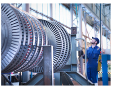
 Large Steam and Gas Turbines with heavy center hung shafts are subject to thermal and/or gravity bow and will be fitted with Turning Gear or Jacking Gear. Zero Speed Monitoring is used to insure that their turning gear is engaged and operating properly. Zero Speed Monitoring is also used to provide a permissive signal to prevent the turning gear from being engaged while the turbine is operating at too high of RPM. Large Steam and Gas Turbines with heavy center hung shafts are subject to thermal and/or gravity bow and will be fitted with Turning Gear or Jacking Gear. Zero Speed Monitoring is used to insure that their turning gear is engaged and operating properly. Zero Speed Monitoring is also used to provide a permissive signal to prevent the turning gear from being engaged while the turbine is operating at too high of RPM.
When a large steam turbine or Gas Turbine is shut down it needs to be immediately placed on Turning Gear to prevent gravity from thermally sagging the shaft in a single direction (down). Electric motor driven Turning Gear is used to keep the shaft rotating at a slow speed usually from 3 to 120 RPM. When the Turbine Shaft has cooled it may be shut down for maintenance but Turning Gear will again be used before startup to straighten any bow that has set in.
In extreme cases the turning gear monitoring has been used to carefully position a shaft with the bow “up” and allowed to rest in that position to let gravity help straighten the shaft.
The turning gear is usually a electric motor that turns a large gear mounted to the turbine shaft and has a very large gear ratio. The Gear mounted to the turbine shaft may have as many as 150 or 180 teeth.
If using the Zero Speed Monitoring System to automatically engage the Turning Gear a redundant system with voting should be used.
STI Vibration Monitoring Inc. provides several methods to retrofit or equip Modern Zero Speed Monitoring to turbines:
Best Practice recommends mounting one or two speed sensors to look at the teeth of the shaft mounted bull gear. This provides a high pulse per revolution that allows STI’s Tachometer products to read very low speeds with excellent resolution. Speed sensors can be of several types including Proximity, Eddy Probe or Inductive, Capacitive or Hall (Magnetic). There also may be existing speed sensors installed that can be used. Explosion Proof Sensors are also available where needed. PLC/DCS Approach:
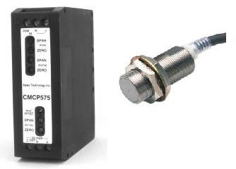 The Turning Gear Speed Sensors are then connected to STI’s CMCP575 Din Rail Mounted Transmitter. 4-20mA signals are sent to the PLCs Field IO. The PLC is programmed to read and alarm on RPM. The actual speed range (0 to n) of the CMCP575 Transmitter is calculated using the turning gear speed desired and number of teeth on the turning gear and is usually set in the 300 to 500 RPM FS Range to insure low end resolution. The Turning Gear Speed Sensors are then connected to STI’s CMCP575 Din Rail Mounted Transmitter. 4-20mA signals are sent to the PLCs Field IO. The PLC is programmed to read and alarm on RPM. The actual speed range (0 to n) of the CMCP575 Transmitter is calculated using the turning gear speed desired and number of teeth on the turning gear and is usually set in the 300 to 500 RPM FS Range to insure low end resolution.
Standalone Approach with Relays and 4-20 mA Output:
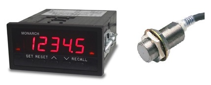 For a standalone system the speed sensors are connected to STI’s CMCP-Tach3. The CMCP-Tach3 is a panel mounted Tachometer that includes a Red LED Display of RPM. High and Low alarms that can be programmed with corresponding Form C relays. The number of pulses per revolution are then programmed into the Tachometer. A 4-20 mA output signal is also available for speed logging at PLC/DCS or Historian. For a standalone system the speed sensors are connected to STI’s CMCP-Tach3. The CMCP-Tach3 is a panel mounted Tachometer that includes a Red LED Display of RPM. High and Low alarms that can be programmed with corresponding Form C relays. The number of pulses per revolution are then programmed into the Tachometer. A 4-20 mA output signal is also available for speed logging at PLC/DCS or Historian.
For help with your Turbine Monitoring or Supervisory application please give us a call or email at STI Vibration Monitoring Inc. in League City Texas at 281/334-0766.
CMCP575 Zero Speed Example:
Turning Gear Speed 6 RPM (0.10 Hz)
Gear Teeth 167
Pulses Per Minute 1,002 PPM (16.7 Hz)
CMCP575 Response 0.031 Hz to 38 kHz Frequency response
As can be seen the frequency response on turning gear (16.7 Hz) is well with the frequency response of the CMCP575 (0.031 Hz to 38 kHz). With the 4-20 mA signal being sent to IO a Range is then selected to get proper resolution. In this case an Engineering Unit Range of 0 to 25 RPM. Alarms can then be set in the PLC/DCS as below.
CMCP575 Setup:
0 RPM x 167 teeth = 0 Hz (Pulses Per Second)
25 RPM x 167 Teeth = 69.583 Hz (Pulses Per Second)
Analog Output:
0 RPM = 4 mA Output
6 RPM = 7.84 mA Output
25 RPM = 20 mA Output
|
