Valve position measurements are an important
aspect of a complete Turbine Supervisory Instrumentation system. Typically, the Main Steam
Control (or Throttle) Valve is always included in the system with other valves added
depending upon the control system incorporated in the turbine design. Addition of a
position transducer to a hand wheel operated throttle valve, which was equipped only with
a graduated scale for indication, will allow more precision in valve positioning.
Valve
position indication is actually a measurement of the amount a valve is closed or
open. This measurement is usually made with a Linear Variable Differential Transformer
(LVDT), but sometimes a Rotary Potentiometer is used for special applications. Nearly all
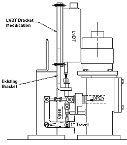
applications require bracket made to attach the transducer and another bracket in physical
contact with the moveable portion of the valve (stem or linkage).
Theory of Operation
LVDT
 LVDTs
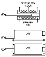
are electromagnetic devices that have three coils of wire wound on a hollow tube and a
metal rod moving inside the hollow tube. The center coil of wire is excited by a supply
voltage which induces a voltage in the other coils as the rod or plunger travels
throughout its range.
When the plunger is centered in its range the induced voltage of the two secondary
coils is equal in magnitude, but opposite polarity. As the plunger moves to either side of
the center position the voltage of one of the secondary coils increases while the other
secondary coil experiences a decreased voltage. DC LVDT's differ from AC LVDT's in that
they are manufactured with an internal carrier generator/signal conditioning module and
only require DC Power to operate.
Rotary Potentiometer
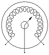
 The rotary potentiometer is a device very similar to a variable resistor. It
has a coil of wire shaped in a arc with a wiper which moves across the wire coil. As the
wiper, which is attached to the valve cam shaft, moves across the coil of wire a differing
voltage is output proportional to the angle at which the wiper is located. The rotary potentiometer is a device very similar to a variable resistor. It
has a coil of wire shaped in a arc with a wiper which moves across the wire coil. As the
wiper, which is attached to the valve cam shaft, moves across the coil of wire a differing
voltage is output proportional to the angle at which the wiper is located.
Special Considerations
Operating Range
STI's CMCP LVDT's, have a range of 1, 2 and 4" with an accuracy
of ±0.5% full scale. A shorter range may be selected by using the center portion of the
standard operating range.
SKF-CM's rotary potentiometer P/N# CMSS30503100 is a direct replacement for GE Catalog
No. 9888323 or equivalent.
Transducer Installation
The body of the LVDT is designed to be rigidly attached to an immoveable location or
bracket with the rod pressing against the valve stem or bracket. Proper installation of
the LVDT involves selecting a location where the operating range is not exceeded and the
LVDT rod has free travel.
For valves having longer strokes (greater than 2 inches), a suitable location along the
valve operating linkage must be selected where the LVDT operating range is not exceeded.
An alternative is to design a custom linkage to achieve the range required. A second
alternative is to install a circular cam to the throttle valve cam assembly and install
the LVDT so that the rod contacts the cam. The latter alternative is not applicable on
smaller turbines which may not have a throttle valve manifold containing several steam
valves intended to open at differing loads.
Rotary potentiometers, by their design, require
that they be installed at the end of the throttle valve cam shaft or valve linkage axle.
The valve axle shaft will require modification to allow the potentiometer shaft to be
clamped rigidly, possibly with a coupling. The potentiometer body must be installed so
that it will not rotate as the valve shaft rotates.
Conduit
Dedicated conduit should be provided in all installations for mechanical protection of the
instrument cable. Rigid conduit is required from the monitor location to the LVDT or
Potentiometer location. The final 2-3 feet of the conduit installation should be completed
with flexible conduit to allow transducer removal.
Measurement Convention
Measurement convention involves determining which direction the valve operates in relation
to the selected transducer location. The CMCP LVDT rod is spring loaded with the rod
forced in the extended direction. The standard installation has the extended orientation
representing 0% indication or valve closed and the fully compressed orientation
representing 100% indication or valve fully open.
Many times the LVDT cannot be installed in the standard configuration and orientation
due to space considerations or other circumstances. This situation should not preclude the
installation because the output signal can be electrically inverted at the monitor
location.
Rotary potentiometer applications follow the same measurement convention argument as
LVDT installations.
Instrument Wire
For LVDT and Rotary Potentiometer applications a 3-wire twisted shielded instrument wire
should be utilized between the monitor location and the LVDT. This wire should be a
continuous run and not be spliced.
The following table is a partial list of Belden® Cables that should be used for the
instrument wire. These part numbers may be cross referenced to equivalent cables from
other manufacturers. The listed cables are polyethylene insulated, twisted, with Beldfoil
shield, drain wire, and PVC jacket.
| Belden® Part Numbers (LVDT) |
|
PN |
Nom. O.D. |
| 18 AWG |
8760 |
0.22" |
| 20 AWG |
8762 |
0.20" |
| 22 AWG |
8761 |
0.18" |
Calibration
The LVDT is designed to be installed so that when the rod is positioned in the center of
its operating range the LVDT output voltage should be 0 VDC. This calibration may be
accomplished by temporarily inserting a 1.0" block under the rod and adjusting the
roller tip, located at the end of the rod, until 0 VDC is obtained at the transducer
output. As the valve is stroked throughout its full range, the LVDT output voltage should
be noted for monitor re-calibration.
Rotary potentiometers are installed so that the potentiometer shaft is attached to the
cam shaft or other rotating shaft with the potentiometer body rigidly held so it does not
rotate. The potentiometer should be adjusted so that when the rotation angle is 0 the
signal output should be 0 VDC. As the valve is stroked throughout its full range, the
output voltage should be noted for monitor re-calibration.
Valve Position Checklist
- Xdcr Type, LVDT Rotary Pot.
- Operating Range
- Transducer Location(s)
- Measurement Convention
- Xdcr Installation Documented
- Correct Instrument Wire
- Flexible Conduit
- Calibration
|

