CMCP575 Speed Transmitters labeled sold after 1/1/2009 feature the new Smart Touch technology which allow users to calibrate the transmitter within 10% of the frequency span simply by depressing the Zero and Span buttons on the front of the unit while inputting the applied frequency range. In order to accurately set the transmitters 4-20mA output additional steps need to be taken. To calibrate the transmitter the following test equipment is required.
Signal Generator
Digital Volt Meter
24 VDC Power Supply
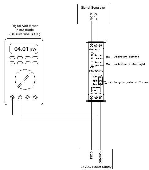
To begin, connect test equipment according to the diagram below and turn on power supply and signal generator and wait 30 seconds for the transmitter to power up and run through the self-check mode.
Operating Speed Calculation: (RPM ÷ 60) x Events Per Revolution
Example: 3600 Max RPM Shaft with 1 Keyway Acting as Sensor Target: (3600÷60) x 1 = 60Hz
300 Max RPM Shaft with a 36 Tooth Gear Acting as Sensor Target: (300÷60) x 36 = 180Hz
The CMCP575 range should exceed the maximum operating speed by a 10% minimum. General calibration ranges are 0-2,500 RPM, 0-5,000 RPM and 0-10,000 RPM though range can be calibrated to any range.
To Adjust the Zero Scale (4mA):
1. Input the minimum frequency level (usually 0 Hz) with an amplitude greater than 50mV
2. Depress the Zero button on the front of the CMCP575, Zero Light will start flashing.
3. Use digital multimeter (DVM) in mA mode to measure the 4-20mA output.
4. If necessary, adjust the Zero screw until the DVM reads 4.00mA
To Adjust for Full Scale/Span Calibration (20mA):
1. Input the maximum calculated frequency level with an amplitude greater than 50mV.
2. Depress the Span button on the front of the CMCP575, Span Light will start flashing.
3. Use digital multimeter (DVM) in mA mode to measure the 4-20mA output.
4. If necessary, adjust the Span screw until the DVM reads 20.00mA
Note:
In order for the CMCP575 to operate the input signal must be greater than 10mV. If the target area does not provide a signal greater than 50mVrms the CMCP575 will not operate correctly.
If the CMCP575 does not provide a steady output while in normal operation the hysteresis may need to be adjusted. While the machine is running at a continuous speed start with the hysteresis screw fully counter clockwise. Turn the adjustment screw clockwise a quarter turn at a time until the output is steady. Verify 4-20mA output calibration after any adjustments.
CMCP575 Calibration Setup
|