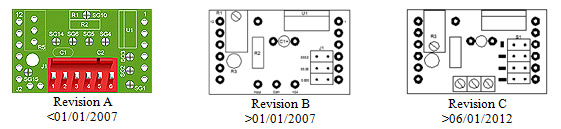
The revision of displays sold prior to 06/01/12 must be identified before proceeding.
If the revision type cannot be identified please contact STI Technical Support for help.
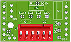
CMCP505 Revision A displays sold prior to 01/01/07 with DIP position selectors and wires soldered directly to the board click here Revision A Calibration Instructions.
CMCP505 Revision B displays sold prior to 06/01/2012 without DIP position selectors and wires soldered directly to the board click here Revision B Calibration Instructions.
CMCP505 Revision C displays sold after 06/01/2012 with a wire termination block and the
Easy CAL feature click here Tech Note 106.
Revision A Calibration Instructions:
CMCP505 Displays sold prior to 01/01/07 can only be recalibrated to a different full scale by changing resistor R2. The existing R2 resistor may be removed using a soldering iron and solder sucker. R2 can then be carefully replaced after shaping and clipping the leads to the proper shape and length. If a solder sucker is not available simply clip out the resistor by cutting the leads close to the resistor body. The leads remaining in the board can then be stood up and new resistor soldered between them. Replacement resistors need to be 1% precision resistor, 1/4 watt.
After installing the proper resistor, apply 5.00 VDC to the input, the full scale value can be adjusted (tweaked) using the 3/4 turn potentiometer accessible through hole in circuit board. Do not force potentiometer over 3/4 turn or permanent damage will result.
If a 5.00 VDC supply is not readily available the voltage output of the CMCP500 Monitor can be used. Using the front selector switch select "Danger" for the danger alarm set point. Increase the set point to 5.00 VDC using a quality digital voltmeter. Adjust display as above then reset danger set point.
Decimal point location is changed by solder gaps SG1 (0.000), SG2 (00.00) and SG3 (000.0). Remove and add solder to the appropriate solder gap.
Engineering Unit Decimal Point Guideline:
in/sec = 0.00 (hundredths)
mm/sec = 00.0 (tenths)
mils = 00.0 (tenths)
microns = 000 (none)
temperature = 000 (none)
Factory recalibration charge is $50.00 plus shipping. Precision resistors are in stock and are available at no charge. Rush or International shipping charges may apply.
| Value |
R2 Value |
Full-Scale Value |
| 050 |
9.1k |
.050, .50, 5.0,
50 |
| 100 |
18.7k |
.100, 1.00, 10.0,
100 |
| 150 |
28k |
.150, 1.50, 15.0,
150 |
| 200 |
37.4k |
.200, 2.00, 20.0,
200 |
| 250 |
47.5k |
.250, 2.50, 25.0,
250 |
| 300 |
57.6k |
.300, 3.00, 30.0,
300 |
| 350 |
68.1k |
.350, 3.50, 35.0,
350 |
| 400 |
78.7k |
.400, 4.00, 40.0,
400 |
| 450 |
909k |
.450, 4.50, 45.0,
450 |
| 500 |
100k |
.500, 5.00, 50.0,
500 |
| 550 |
113k |
.550, 5.50, 55.0,
550 |
| 600 |
124k |
.600, 6.00, 60.0,
600 |
| 650 |
137k |
.650, 6.50, 65.0,
650 |
| 700 |
147k |
.700, 7.00, 70.0,
700 |
| 750 |
160k |
.750, 7.50, 75.0,
750 |
| 800 |
174k |
.800, 8.00, 80.0,
800 |
| 850 |
187k |
.850, 8.50, 85.0,
850 |
| 900 |
200k |
.900, 9.00, 90.0,
900 |
| 950 |
215k |
.950, 9.50, 95.0,
950 |
| 1000 |
226k |
1.000, 10.00, 100.0,
1000 |
| 1100 |
255k |
1.100, 11.00, 110.0,
1100 |
| 1200 |
287k |
1.200, 12.00, 120.0,
1200 |
| 1300 |
316k |
1.300, 13.00, 130.0,
1300 |
| 1400 |
357k |
1.400, 14.00, 140.0,
1400 |
| 1500 |
390k |
1.500, 15.00, 150.0,
1500 |
| 1600 |
430k |
1.600, 16.00, 160.0,
1600 |
| 1700 |
470k |
1.700, 17.00, 170.0,
1700 |
| 1800 |
511k |
1.800, 18.00, 180.0,
1800 |
| 1900 |
560k |
1.900, 19.00, 190.0,
1900 |
| 1999 |
604k |
1.999, 19.99, 199.9,
1999 |
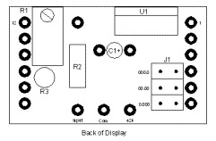
Revision B Calibration Instructions:
CMCP505 Displays sold after 01/01/07 and before 06/01/2012 may be calibrated in the field for a full scale display reading of 00.1 to 1.000. Displays are calibrated at the factory per order requirements. If the full scale range of the CMCP500 Series Monitor is changed in the field the display must be recalibrated to the new full scale range. For CMCP505 displays sold prior to 01/01/07 the R2 fixed resistor must be changed. Using a 5.00 VDC source simply rotate R Clockwise to increase the full scale display amount and counterclockwise to decrease the display amount. The display can be adjusted from 001 to 1000. R3 can be used for trimming if necessary and is accessible through hole in lower left of board. Decimal location is changed by moving the jumper located in lower right corner when viewing back of display. Decimal position can be selected in any of three (3) positions, 00.0, 0.00 and 0.000. The following should be used as a guide to prevent too high of resolution and rapidly changing digits.
Engineering Unit and Decimal Points:
in/sec = 0.00 (hundredths)
mm/sec = 00.0 (tenths)
mils = 00.0 (tenths)
microns = 000 (none)
temperature = 000
If a 5.00 VDC supply is not readily available the voltage output of the CMCP500 Monitor can be used. Using the front selector switch select "Danger" for the danger alarm set point. Increase the set point to 5.00 VDC using a quality digital voltmeter. Adjust display as above then reset danger set point.
|